NanoBoard 3000 の仕様(販売終了)
NanoBord 3000 では特定の FPGA デバイスを搭載した 3種類の製品が用意されています。
- Host (NanoTalk) Controller による FPGA のサポート
| 型名 |
FPGAベンダ |
FPGAデバイスファミリー |
搭載デバイス |
| NanoBoard 3000XN |
Xilinx |
Spartan-3AN |
XC3S400AN-4FGG400C |
| NanoBoard 3000AL |
Altera |
Cyclone III |
EP3C10F256C8N |
| NanoBoard 3000LC |
Lattice |
LatticeECP2 |
LFE2-12E-5FN256C |
| 型名 |
FPGAベンダ |
FPGAデバイスファミリー |
搭載デバイス |
| NanoBoard 3000XN |
Xilinx |
Spartan-3AN |
XC3S1400AN-4FGG676C |
| NanoBoard 3000AL |
Altera |
Cyclone III |
EP3C40F780C8N |
| NanoBoard 3000LC |
Lattice |
LatticeECP2 |
LFE2-35SE-5FN672C |
- One 100-way ペリフェラルボード コネクタ (
'NANOCONNECT' インターフェース)
- スイッチ付き5V DC power コネクタ
- Altium NanoTalk USB 2.0 PC インターフェース
- 4x シリアル SPI Flash メモリ デバイス:
- ホストコントローラ用のプライマリブートイメージを含む
- ホストコントローラ用のゴールデンブートイメージを含む
- User FPGAにより使用可能な2つのFlash (ブート/組込み使用)
- システム JTAG 書き込み専用ポート
- ボード ID と関連情報を格納する為の 1-Wire® メモリデバイス
- 6 ~ 200 MHz のプログラマブルクロック (Altium Designer 又は付属の Soft Designよりアクセス可能)
- 20MHz 固定のリファレンスクロック
- 3V バックアップバッテリ付き SPI Real-Time Clock
- 1.2V、 1.8V、 2.5V と 3.3V に調整可能な電圧レギュレータ
- GND を含む全ての供給可能な電源のテストポイント
- User FPGA によりアクセス可能なメモリ
- 256K x 32-bit common-bus SRAM (1MByte)
- 16M x 32-bit common-bus SDRAM (64MByte)
- 8M x 16-bit common-bus 3.0V ページモード Flash memory (16MByte)
- Dual 256K x 16-bit independent SRAM (各512KByte)
- ホストコントローラ FPGA によりアクセス可能なメモリ
- 256K x 16-bit independent SRAM (512KByte)
- LED アレイ、 8 RGB LEDS
- 5 generic プッシュボタン スイッチ
- 4-channel 8-bit ADC, SPI-compatible
- 4-channel 8-bit DAC, SPI-compatible
- 4x isolated IM Relay channels
- 4x PWM power drivers
- Screw terminal headers for ADC/DAC/Relay/PWM interfaces
- S/PDIF interface
- SD (Secure Digital) card readers:
- One for use by the Host Controller FPGA
- One for use by the User FPGA
- Dual 18-way (20 pin) I/O expansion headers with power supply selection links
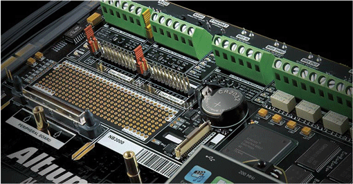
- User prototyping area
- SVGA interface (24-bit, 80MHz)
- 10/100 Fast Ethernet interface
- USB 2.0 High-Speed interface
- RS-232 Serial Port – DB9M
- RS-485 Serial Port – ‘RJ45’
- PS/2 Mini-DIN Mouse Port
- PS/2 Mini-DIN PC Keyboard Port
- 240 x 320 TFT LCD with touch screen
- 37-pin TFT connector
- Resides on separate satellite PCB, attached to motherboard through a 1.8″ ATA/IDE connector
- 12-bit SPI touch screen controller
- 8-way DIP-switch
- USB hub:
- 3x USB A-type connectors
- ISP1760 Hi-speed USB Host Controller
- Stereo 2W audio power amplifier with 3.5mm test input jack and DC volume control
- 24-bit Stereo Audio CODEC with I2S-compatible interface
- Analog audio input: Stereo line in
- Analog audio output: Stereo line out
- Digital audio data: Transfer over I2S bus
- Audio mixer (L and R) for combining audio sources:
- Line Out from Host Controller (Delta-Sigma DAC output, driven by FPGA)
- Line Out signal wired from peripheral board socket
- Line Out signal wired from audio CODEC
- Buzzer output from User FPGA design
- Stereo audio jacks (3.5mm):
- Line In / Line Out
- Headphones
- Speaker sockets for direct connection of speakers, resident on a separate (attached) board
- Status LEDs:
- ホストコントローラのステータス用
- User FPGA 電源とプログラムのステータス用
- Diagnostics interface – PCI Express (PCIe) edge connector for connection of automated test equipment (ATE)
- 1.8″ ATA/IDE connector providing access to user LED and generic switch I/O
- Test/Reset ボタン
ブロックダイアグラム

外観
全体像

タッチパネル

ペリフェラルボード コネクタ

電源・I/O コネクタ

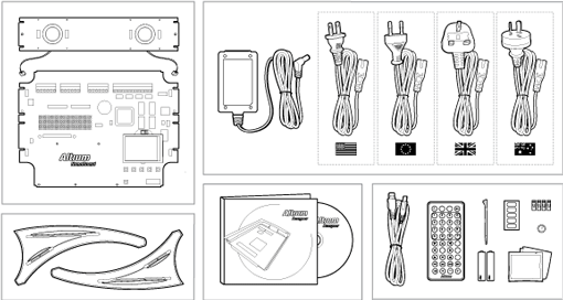
本体・付属品

そのら
NanoBoard 3000 についての不明点は Altium 問合せ・リクエストフォーム からお問合せください。


